PCB and Web Serives; Part 2
Printed Circuit Board
As described in Part 1 of this series, we need only a few signals to perform AC Dimming; a zero cross detection signal, and the output to our switch. The circuit on the first image shows the components used. The H11AA11 sends a trigger signal every time the AC circuit crosses the zero point. It keeps the AC and low voltage DC under optically isollation, meaning your microcontroller is safe.With this signal, the controller can output a signal to the appropiate TRIAC. Each TRIAC is optically isolated to keep the controller safe and also has an LED indicator on the low voltage side to see how much dimming is being applied.
The circuit was then layed out in the schematic in picture 2 and printed. Picture 3 shows the assembled PCB along with the micro controller used, an ESP8266 board, and an AC to DC power supply.
AWS
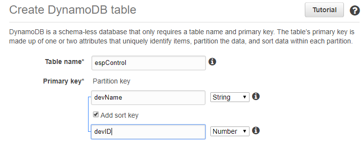
Now that the electronics are out of the way we can focus on the web services. A DynamoDB table was used to hold the state of the swtiches and a Lambda function was created to update the DynamoDB from an Alexa command. The processor queries the DynamoDB every few seconds, reads the values in the tables and updates the dim value of each channel if necessary.A more detail explanation on how to set everything up along with the code can be found here: https://gitlab.com/arturju/smartPowerStrip
Comments
The code used to make the ESP8266 chip read and write to a DynamoDB is still under development so there may be some bugs if anything is changed.
The free tier of AWS let's you query the DB only a certain number of times a second, exceeing this number of requests will cause them to charge your account. So make any changes in delays or update rates with caution.

