Galilean Thermometer Displacement Calculator
Boundary Conditions
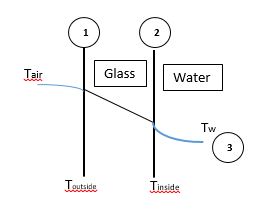
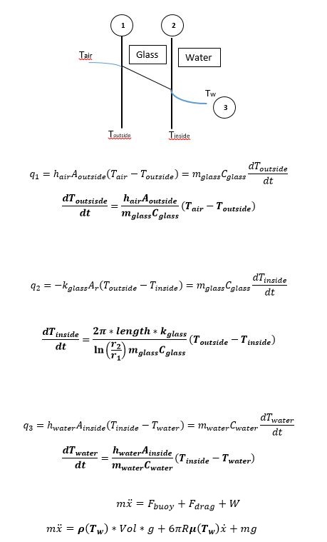
The first step in solving this problem is to set up the appropriate boundary conditions. In this problem, there are three points where the the temperature is changing: the outside of the glass, the inside of the glass, and the water (assume same as bulb); 1, 2, and 3 respectively. The location of the bulb will depend on forces created by the changing temperature of the water, more on this later.We also have to set initial conditions for each of those variables. Using the 1st law of thermodynamics, the equations for heat conduction and convection, the heat capacity formula, and Newton's second law we can get equations for the rate of change of those 3 points.
Defining Constants
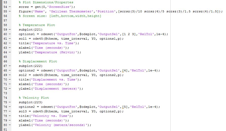
The next step is defining all the constants. Masses and surface areas depend on radii specified for the bulb and cylinder. For simplicity, some variables like viscosity can be given constant values even though their exact value changes with temperature. After assigning values for these we get 4 variables in a system of differential equations.MATLAB does exceptionally well solving systems of equations and has no problem solving this one. Properties like error tolerances and plot styles are currently hard coded. MATLAB's ode45 function is used to solve the system of differential equations.
The program basically takes the initial conditions (t0) to calculate temperature and displacement at t1. It then uses values found at t1 to calculate for t2, then t2 values to find t3 and so on until the time specified is reached.
GUI
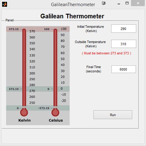
Once the equations are in place I created a GUI to make it easier to use and change some parameters. During 1atm pressure, equations for the density of water are only valid between 273 and 373K so the outside air temperature and initial inside temperature are limited by that range. The user can also specify how many seconds to run the simulation for.
A picture of Kelvin and Celcius scales side by side was added to make the values more relatable.
Testing Functionality
The green line on the top left graph is the temperature of the glass cylinder- the inner and outer temperatures are almost identical but difference can be seen after zooming in. The red line is the temperature of the water and the bulb. As it's expected, the glass reaches the temperature of the outside first and then the water.
The velocity of the bulb will always approach it's steady-state value, and in the case that the steady-state velocity is zero, the displacement also reaches a steady value as expected.
You can download the source code by clicking here.