IoT Power Meter
Preface
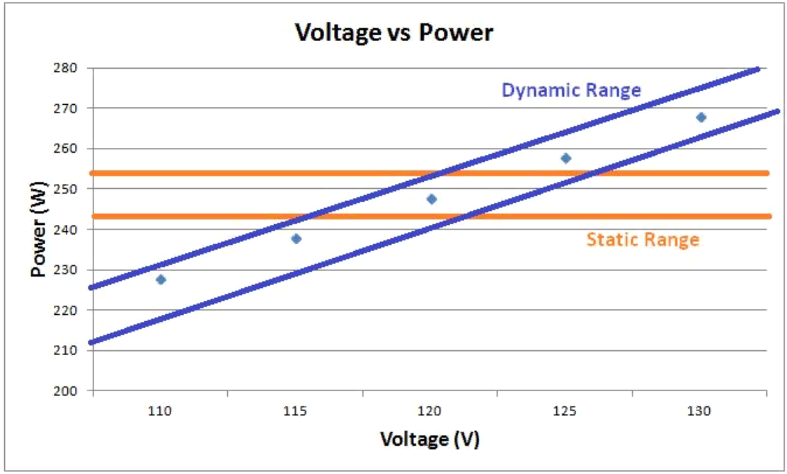
We constantly perform wattage tests on devices to test for general functionality and the majority of these power specifications are given at a constant voltage of 120Vac. Unfortunately, line voltages rarely stay constant while drawing power and solutions for maintaining 120Vac can become very expensive.An alternate (and cheaper) solution is to extrapolate what the power consumption would be at different voltages given their 120Vac rating (this would assume a constant resistance on the device being tested which is not always the case but is acceptable for small voltage fluctuations) and use a dynamic range of acceptable wattage values.
Hardware
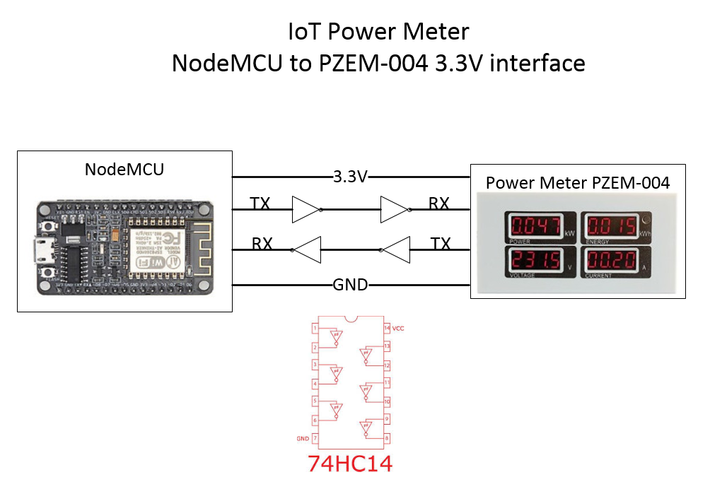
The hardware used was a NodeMCU (based on the ESP8266) and a TTL ready power meter, BAYITE-PZEM-004. The signal had to be conditioned with a 74HC14 chip beause the NodeMCU operates at 3.3V and the power meter at 5V. Once this was set up, the only thing left to do was program the micro-controller to parse the meter's data and display it in a meaningful way.You can view the code and other documentation here:
Video coming soon
Demo
In this demo the power meter is connected to an autotransformer and the voltage is being controlled manually to simulate a voltage drop on the line.
I found that if the NodeMCU is queried too often it looses connection. Once per second seems to be a good balance between 'real time updates' and abiity to connect from multiple clients.