Wheel Tester and DAQ
The Goal
The objective of this project was to create a way for an operator to test iRobot wheels quickly and reliably. The previous method of testing involved using the unit's built-in test function but this process was confusing and took 1 -2 minutes to perform.The new test had to account for all the parameters the wheel is tested for in the original test: RPM, Stall Current, and Microswitch functionality. A microcontroller was used to control the rotation of the wheels, actuators, LEDs, current and encoder pulse readings. The mechanical design tries to minimize the number of moving parts and has an arm to act as a break when checking the stall current.
Project Schematic
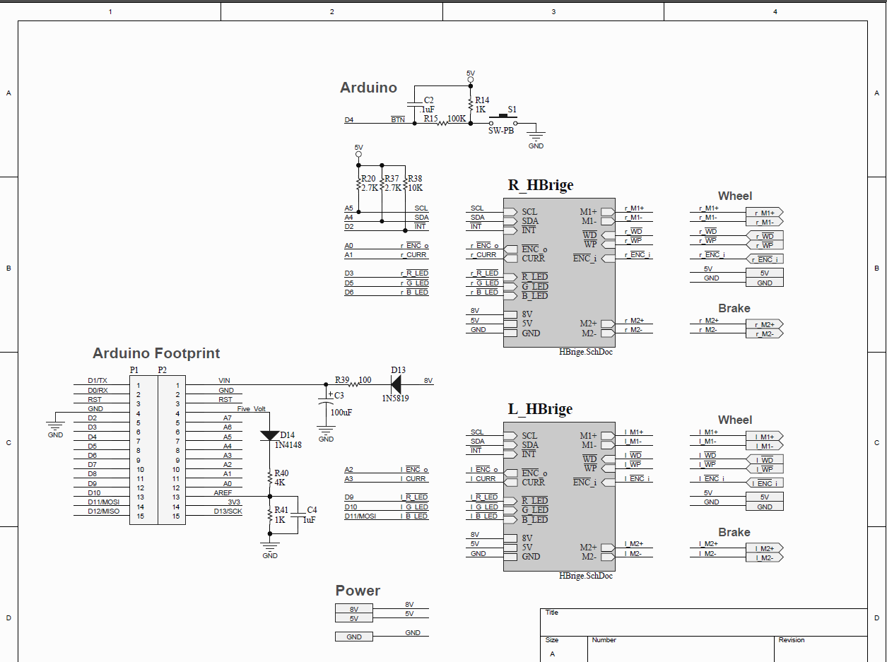
The schematic on the picture shows an almost finalized version of the configuration for this project. We can see the Arduino inputs are the current (analog value) and the encoder readings. There is also a voltage divider connected to the Aref pin so that the current readings can have a better resolution.An I/O expander was used with the I²C protocol to control the H-bridge and take the wheel switch and wheel presence as inputs. There is also a pair of RGB LEDs so that the unit can light up red or green depending on the test result. Lastly, a single button is added to re-test the wheel if needed.
Modeling with SolidWorks
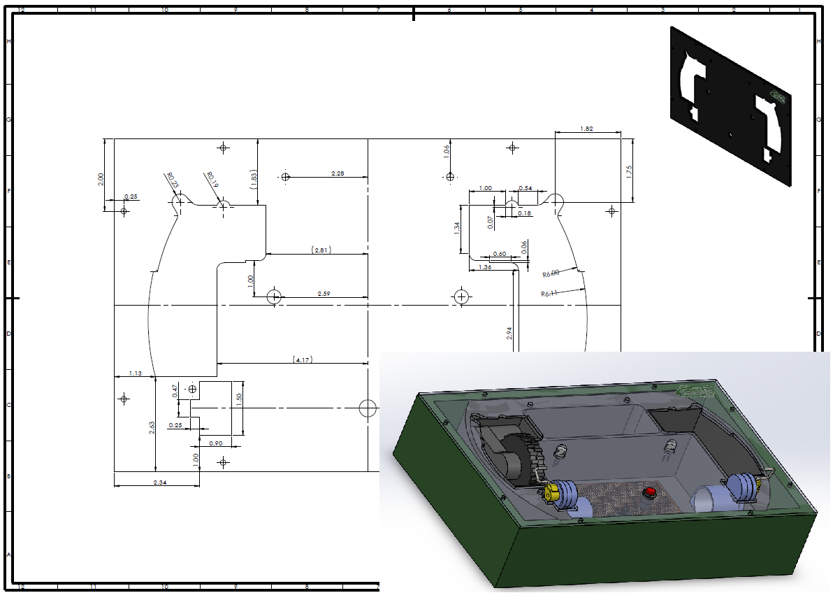
To get an idea of what the final product would be like I used SolidWorks to draw the main components of the system. What really needed an accurate drawing was the cover for the top of the unit. This would act as a guide so that its only possible to insert the wheel in the correct orientation.Holes for the break mechanisms, LEDs, and button were also made on the drawing. This part was to be constructed using black acrylic.
Embedded System
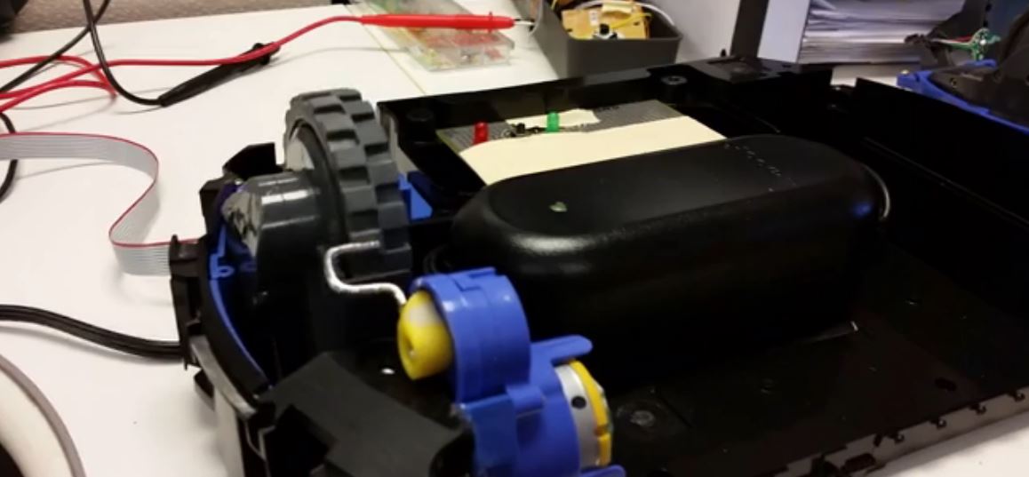
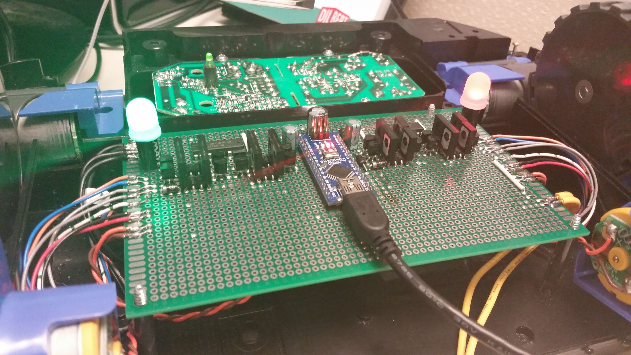
An Arduino Nano microcontroller was used to control this system. The PCB was placed on the top of a cut out iRobot chassis that doubled a secondary guide for the wheels.The circuit behind the PCB with the controller is a power supply used to power the whole system; wheels, actuators, LEDs and the controller itself. It also conveniently screws on the chassis and protrudes the needed components from the top cover to minimize movement and make maintenance easy.
C# Application
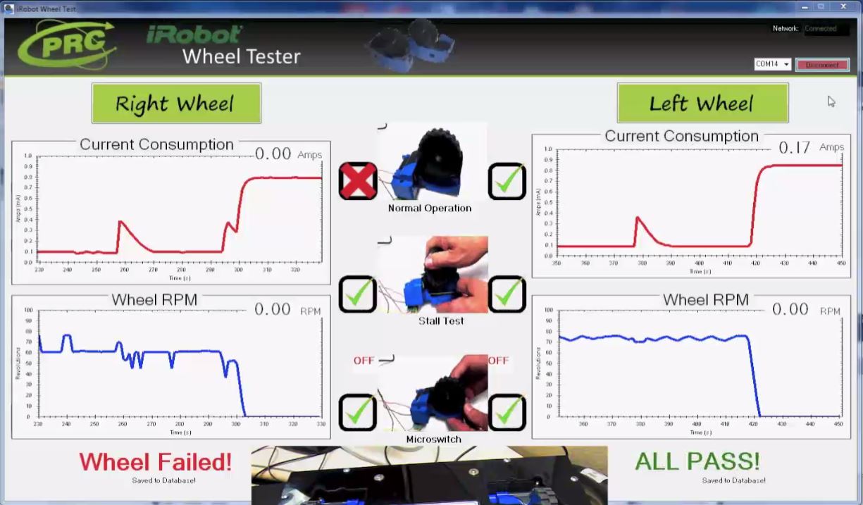
In order to extend the capabilities of the wheel tester a C# application was needed. This allows for an easy to understand GUI for the operator and for database connectivity to save the test results.
The program also allows the operator to see the test results real time as well as visually inspect the data on the graphs for any anomalies. At the end of all three tests the program will also display a single pass or fail for faster use. The testing sequence takes 8 seconds.
Putting it Together
When all the sub systems are integrated the result is an easy to use and intuitive wheel tester. Because of the wheel presence circuit on the I/O expander the controller knows when the wheel is placed and the test can begin automatically.The video shows the left and the right wheel being tested and what the program displays while the test is being performed. Also shows how the test results are being stored using SQL Server.